Hardware Overview
This relay array controls (closes/opens) a 220V circuit.
This relay array is a direct development and expansion of the Power & Networking project.
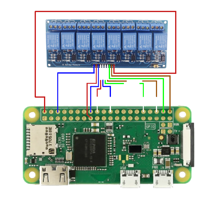
Figure 4: Comprehensive Wiring for Optoisolated 8 Relay Module
Wiring Matrix
Connect the optoisolated 8 relay module to the Pi Zero 2 W using the following GPIO configuration.
| Optoisolated 8 Relay Module[2] | Pi Physical Pin | Wiring |
|---|---|---|
| Vcc (+) | Pin 1 (5V) | Orange |
| Relay 1 | Pin 15 (GPIO 3) | Orange |
| Relay 2 | Pin 16 (GPIO 4) | Blue |
| Relay 3 | Pin 18 (GPIO 5) | Orange / White |
| Relay 4 | Pin 22 (GPIO 6) | Blue / White |
| Relay 5 | Pin 32 (GPIO 26) | Green / White |
| Relay 6 | Pin 36 (GPIO 27) | Brown / White |
| Relay 7 | Pin 38 (GPIO 28) | Green |
| Relay 8 | Pin 40 (GPIO 29) | Brown |
| Ground | Pin 6 (GND) | Blue |
List of Materials (BOM)
Referenced components used in this manufacturing process.
| ID | Item | Pinnout Diagram | Description/Source |
|---|---|---|---|
| [1] | Raspberry Pi Zero 2 W | Pinout | Available on Emag. |
| [2] | Optoisolated 8 Relay Module | Pinout | Available on Optimus Digital. |
)
)