Hardware Overview
This Sensor Node features a comprehensive sensor suite designed for environmental monitoring and automated security.
This Sensor Node is a direct development and expansion of the Power & Networking project.
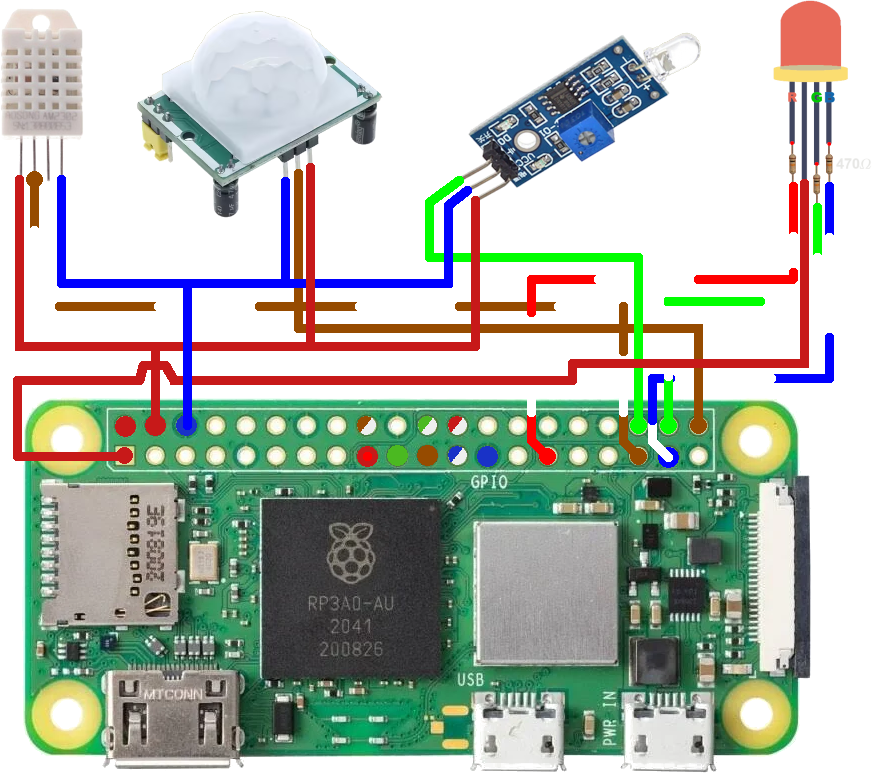
Figure 4: Comprehensive Wiring for PIR, Photodiode, DHT22, and RGB LED
Wiring Matrix
Connect the sensors to the Pi Zero 2 W using the following GPIO configuration.
| DHT22 (Temp/Humidity)[1] | Pi Physical Pin | Wiring |
|---|---|---|
| Vcc (+) | Pin 2 (5V) | Orange |
| Data | Pin 35 (GPIO 19) | Brown / White |
| Null | not connected | |
| Ground | Pin 6 (GND) | Blue |
| PIR (Movement)[2] | Pi Physical Pin | Wiring |
| Vcc (+) | Pin 2 (5V) | Orange |
| Out | Pin 40 (GPIO 21) | Brown |
| Ground | Pin 6 (GND) | Blue |
| Photodiode Module[3] | Pi Physical Pin | Wiring |
| Vcc (+) | Pin 2 (5V) | Orange |
| Ground | Pin 6 (GND) | Blue |
| TTL Sihnal Output | Pin 36 (GPIO 16) | Green |
| Analog Signal Output | not connected | |
| RGB Led[4] | Pi Physical Pin | Wiring |
| Blue | Pin 37 (GPIO 26) trough 470Ω resistor[7] | Blue / White |
| Green | Pin 38 (GPIO 20) trough 470Ω resistor[7] | Green / White |
| Common Anode | Pin 1 (3.3V) | Orange |
| Red | Pin 29 (GPIO 5) trough 470Ω resistor[7] | Orange / White |
| BroadLink Command Hub[5] | Pi Physical Pin | Wiring |
| Vcc | Pin 2 (5V) | Orange |
| Ground | Pin 6 (GND) | Blue |
Assembly & Wiring Instructions
Sensor Wiring Standards
- Standard Leads: Use wires of approximately 5-6 cm to connect the sensors (PIR, DHT22, etc.) to the Raspberry Pi GPIOs.
- Photodiode LED Mod: Desolder the photodiode from the module and reconnect it using a 6 cm cable. This allows the LED to be positioned on the ornament faceplate while the module remains internal.
BroadLink Command Hub[5]
- Cable Prep: Use a standard Mini-USB cable and cut it to approximately 10 cm.
- Internal Wiring: Strip the cable and use only the red (+5V) and black (GND) wires for soldering to the Pi's power rails.
Hardware Calibration & Tuning
To ensure the reliability of the remote node, both the PIR and LM393 modules must be physically calibrated to match the deployment environment.
PIR Motion Sensor[2]
The PIR module features two orange potentiometers:
- Sensitivity (Sx): Adjusts the detection range (3m to 7m). Turn clockwise to increase distance.
- Time (Tx): Sets the "High" signal duration after detection. For this project, it is recommended to set this to the minimum (fully counter-clockwise) to allow the software to handle timing logic.
Photodiode Module[3]
This module uses a comparator to determine "Light" vs "Dark" thresholds:
- Threshold Potentiometer: Adjust this while monitoring the on-board digital output LED.
- Calibration: Turn the screw until the LED just turns off under normal ambient light. This ensures the Pi receives a
HIGHsignal only when the light drops below that specific level.
List of Materials (BOM)
Referenced components used in this manufacturing process.
| ID | Item | Pinnout Diagram | Description/Source |
|---|---|---|---|
| [1] | DHT22 | Pinout | Available on Sigmanortec. |
| [2] | PIR | Pinout | Available on Sigmanortec. |
| [3] | Photodiode Module | Pinout | Available on Optimus Digital. |
| [4] | RGB LED 5MM 4-PIN COMMON ANODE, OPAQUE | Pinout | Available on Sigmanortec. |
| [5] | BroadLink RM4 Pro | Available on Emag. | |
| [6] | Raspberry Pi Zero 2 W | Pinout | Available on Emag. |
| [7] | 470Ω Resistor | Available on Sigmanortec. |
)
)
)
)
)