Project Purpose & Requirements
Why This Exists
This sensor node is one component of a larger open-source ecosystem designed to unify a home's physical infrastructure — underfloor heating, heat recovery ventilation, solar thermal, motorized shading — into a single adaptive intelligence layer. Each node feeds real-time environmental data into a decentralized MQTT architecture, replacing manual control with passive, predictive comfort. The full system architecture is described here: Smart Home Architecture
Why Custom Hardware?
This module was designed to address the shortcomings of existing systems: no cloud dependency, no subscription fees, and no vendor lock-in. It reuses existing home infrastructure — standard junction boxes and UTP conduits — eliminating the need for additional wiring. Sensors are interchangeable across different deployment scenarios, and all data is exposed directly to an open MQTT bus, giving the system full control over its own logic without relying on third-party platforms.
The Objective
The module transforms a standard 10x10cm junction box into a centralized monitoring and command point for home automation.
Movement Detection, Temperature and Humidity Monitoring, Ambient Light Sensing, WiFi Repeater
Modular Design: easy addition or removal of sensors and modules
BroadLink integration: active bridge capable of executing IR or RF commands
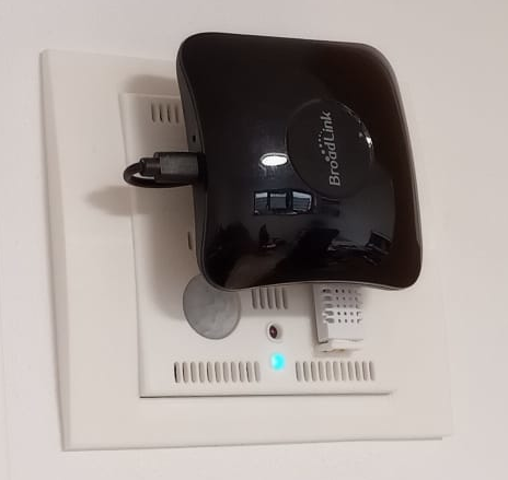
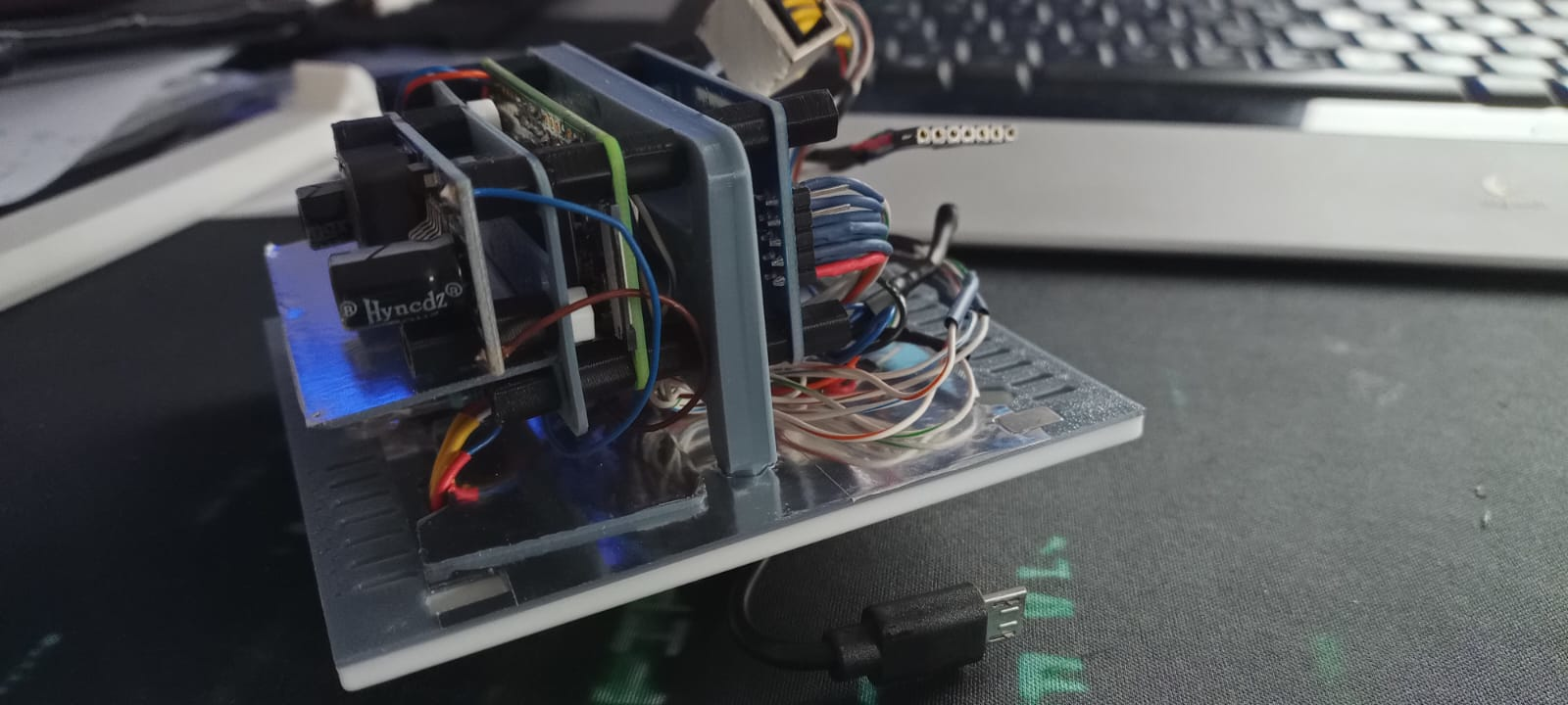
The completed module
Step 1: Wall Mounting & Ornament Installation
The manufacturing process begins with preparing the physical site. We use a custom-designed mounting ornament that bridges the gap between the internal electrical box and the external sensor faceplate.
1.1 Site Preparation & EMI Shielding
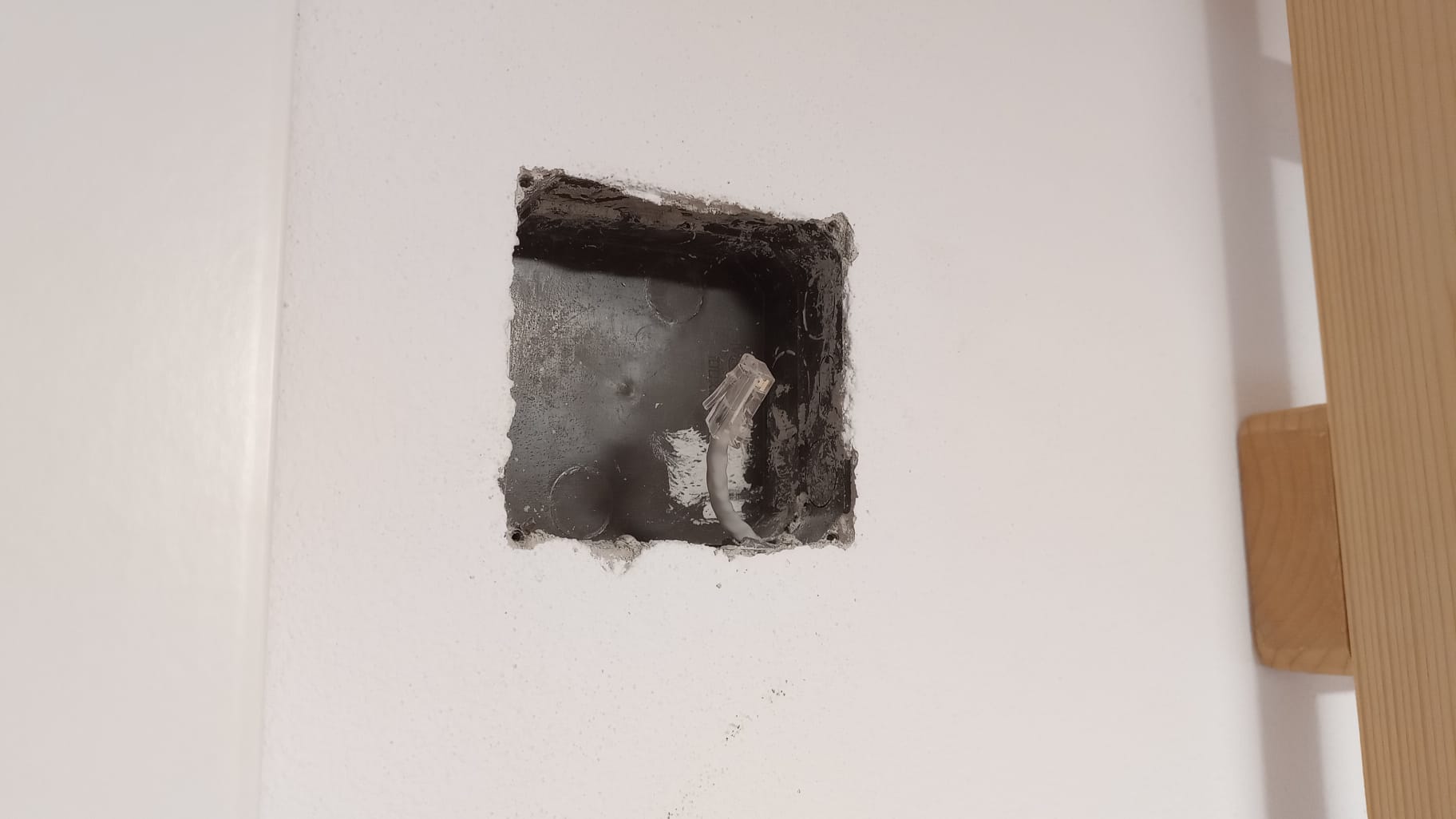
The first stage involves selecting the appropriate wall junction box and clearing any debris. If the box contains active high-voltage (230V) lines, they must be strictly isolated for safety.
- EMI Shielding: Wrap all high-voltage power cables in aluminum foil to prevent Electromagnetic Interference (EMI) from affecting sensor accuracy.
- Electrical Insulation: ⚠️ Important: Wrap the aluminum foil[6] entirely in electrical insulation tape. This prevents the foil from accidentally touching and short-circuiting any sensor components or GPIO pins.
- Grounding: Connect the aluminum shielding to the existing house grounding wire. If no ground is present, pull a dedicated grounding cable through the conduit alongside the UTP cable.
- Infrastructure: Pull the UTP cable through the conduit to provide the unified internet connection and 12V power via the Passive PoE system.
1.2 Infrastructure & Power Placement
Successful deployment requires a centralized hub for power and data distribution, typically located in a Technical Room or media cabinet.
- Voltage Drop Compensation: The 12V/24V transmission is stepped down to a stable 5.1V at the destination, making the system immune to voltage fluctuations caused by long cable distances.
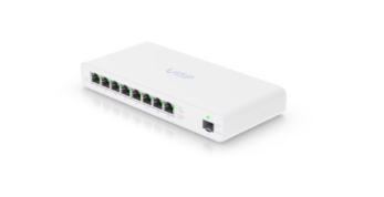
- The Switch: Use a UISP Switch Plus[8] for both power and internet distribution. This hardware is capable of delivering the required passive PoE while managing the network backbone for all components.
1.3 Ornament Fabrication & Magnet Fitting
After the main support frame is secured, the next phase focuses on the fabrication of the custom sensor mounting elements.
- 3D Printing: Print the ornament using the provided model [1], use PLA[3] filament. Once finished, clean the part by removing support structures and any debris to ensure a high-quality aesthetic finish.
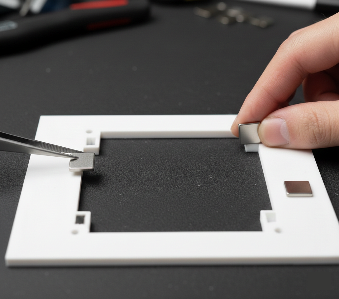
- Magnet Installation: Insert neodymium magnets[7] into the specially designed orifices within the ornament's structure.
- Magnetic Polarity: ⚠️ Critical Step: All magnets must be installed with the exact same polarity facing outwards. This alignment is essential to ensure the outer sensor faceplate attaches correctly and remains interchangeable.
1.4 Securing the Frame
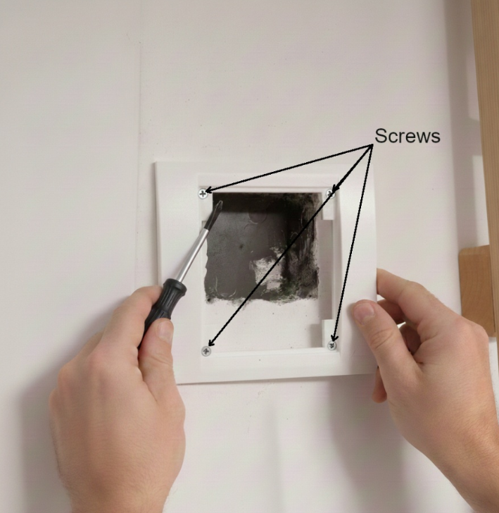
Position the frame over the wall aperture. Secure it using the four corner screws.
This frame provides the structural integrity needed to hold the sensor stack. Its magnetic base then facilitates a 'snap-on' sensor installation, providing sufficient structural integrity to support the sensor's weight.
Step 2: Electrical Component Manufacturing
The heart of the module consists of two main electronic layers. Detailed assembly instructions and pinout diagrams for these components are located in their respective project files.
2.1 Power & Network
Focuses on the Raspberry Pi Zero 2 W, the ENC28J60 Ethernet module, and the 12V/24V-to-5V Passive PoE step-down logic.
View Power Assembly Project2.2 Sensor Node & Command Hub
Covers the wiring and calibration of the PIR, DHT22, and photodiode sensors, as well as the integration of the BroadLink command module.
View Sensor Assembly ProjectStep 3: Faceplate Fabrication
The following image details the internal arrangement of the sensor node. Each numbered component corresponds to a specific part of the power, networking, or sensing layers.
3.1 Faceplate Fabrication
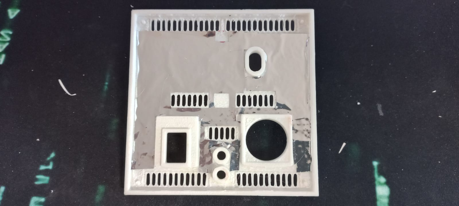
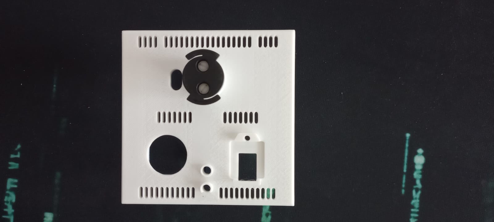
- 1. Print all the module components[2] and clean all parts by removing support structures. Use PLA[3] for the front, PETG HF[4] for the back plate and internal component, and PLA Tough+ [5] for the screws.
- 2. The printer makes a few minor mistakes when printing the screw/spacer threads, so mount/unmount each screw/spacer into another - hardening and forming the filament this way. It doesn't really matter if it's perfect, because the weight they're holding is small.
- 3. Stick the aluminum foil[6] on the inside of the plate so that it does not touch the ventilation holes or the protruding elements.
- 4. Fix the broadlink bracket with screws to the front plate
- 5. Insert neodymium magnets[7] into the specially designed orifices. All magnets must be installed with the exact same polarity facing outwards.
- 6. Fix the back and front together using plastic glue
3.2 Assemble the components
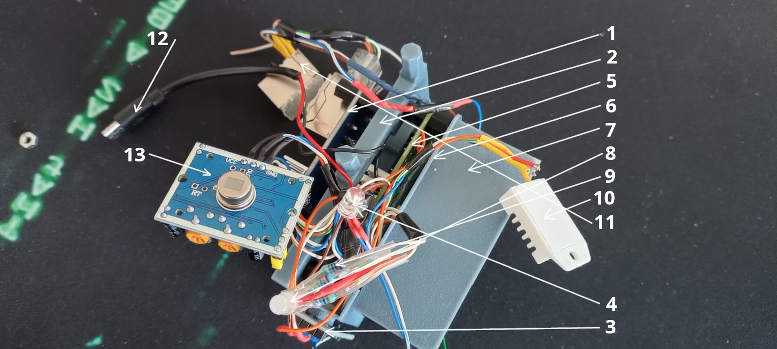
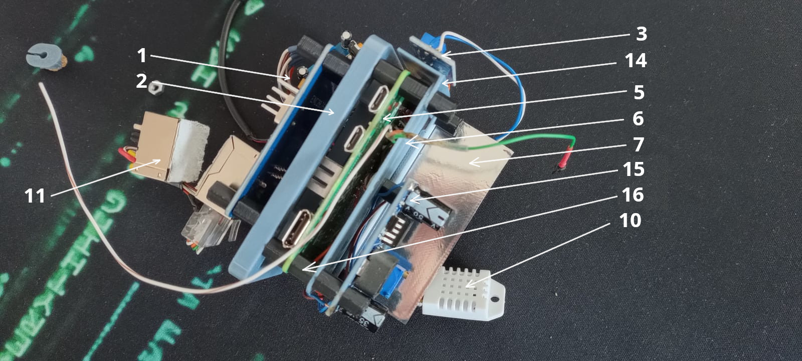
- 1. ENC28J60 Ethernet Module
- 2. Electronics support
- 3. Photodiode Module
- 4. Photodiode
- 5. Raspberry Pi Zero 2 W
- 6. Electronics separator
- 7. Heat shield
- 8. RGB Led
- 9. 470Ω Resistor (s)
- 10. DHT22 Sensor
- 11. Passive PoE Connector
- 12. Mini USB power connector for Broadlink
- 13. PIR Sensor
- 14. Photodiode Module support
- 15. LM2596
- 16. M3 Spacer
3.4 Fix all together
- 1. Mount the front of the PIR sensor
- 2. Stick aluminum foil[6] on the back of the DHT22 sensor, pass it through the hole on the board, attach the plugs both at the back and front, put a little silicone so that air cannot pass between the cables
- 3. Mount the photodiode in the top hole
- 4. Mount the RGB Led in the bottom hole
- 5. Pull the power cable for the broadlink through the hole, plug it with the printed plug
- 6. Fix the electronics support on the board with a drop of glue
Step 4: Software Installation & Configuration
Write the provided operating system image[9] to an 8G SD card[10], insert it into the slot on the raspberry pi. All operating system configuration is described in the Operating System Project
Thermal Stability & System Reliability
The stability of the system relies on maintaining an optimal operating temperature for the mounted sensor.
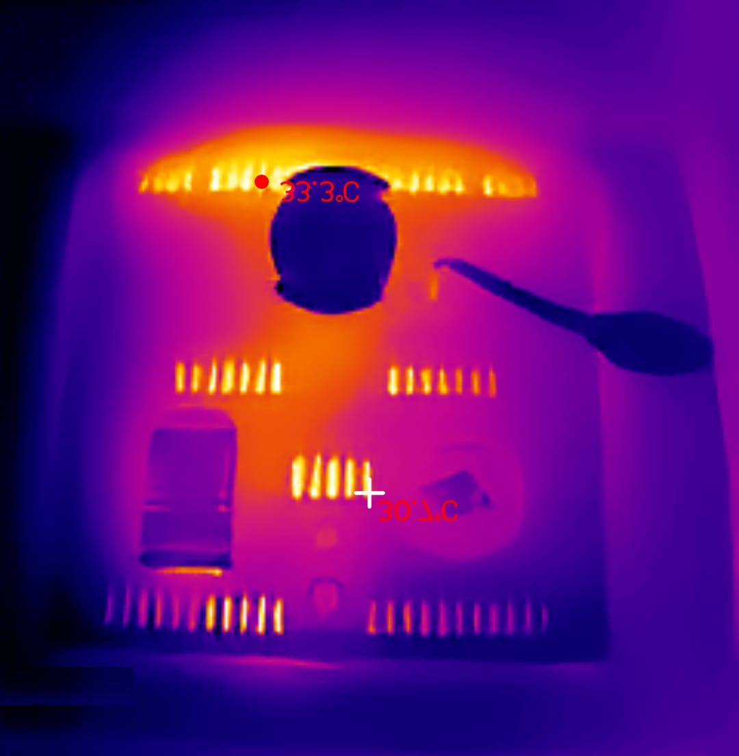
Thermal analysis showing stable board temperature
The most significant engineering problem in this module is sensor accuracy. The Raspberry Pi Zero operates continuously at 45°C - 55°C inside a compact 10x10cm enclosure, creating a micro-climate that corrupts ambient temperature readings — the DHT22 sensor measures the heat trapped inside the box, not the actual room temperature.
The solution is a multi-chambered thermal design: the Raspberry Pi and the DHT22 sensor are physically separated by a dedicated printed heat shield and an electronics separator layer. Combined with passive ventilation geometry built into the faceplate, the board surface stabilizes at 30°C after 48 hours of continuous operation — reducing thermal interference to a correctable 2°C offset.
The current iteration uses PLA and PETG HF, which perform adequately but approach their thermal limits in sustained high-temperature environments. The next design revision will transition to ASA-CF or PA-CF filaments, offering superior heat deflection and long-term dimensional stability.
Live Interactive Assistant
Hello! I'm the assistant for the Open Smart Home Ecosystem project.
I can answer questions about the sensor node manufacturing, the system architecture, bill of materials, software setup, thermal design, and the overall project philosophy. What would you like to know?
List of Materials (BOM)
Referenced components used in this manufacturing process.
| ID | Item | Description/Source |
|---|---|---|
| [1] | Wall Ornament | Download 3mf File |
| [2] | Faceplate, accesories | Download 3mf File |
| [3] | PLA Basic | Available on Bambu Store. |
| [4] | PETG HF | Available on Bambu Store. |
| [5] | PLA Tough+ | Available on Bambu Store. |
| [6] | Aluminum adhesive tape | 50mmx50m. Available on Tehnic Expert. |
| [7] | Neodymium Magnets | 8x5x3mm N52 Grade. Available on Hornbach. |
| [8] | UISP Switch Plus | Available on EU Store. |
| [9] | Operating system image | Download img |
| [10] | Memory Card 8B | Available on ForIT. |